![]() Tel: +86-15876591363
Tel: +86-15876591363 ![]() Email: Tony@aputon-transformer.com
Email: Tony@aputon-transformer.com

- English
- 简体中文
- عربي
- БеларускаяName
- Русский язык
- Français
- ខ្មែរKCharselect unicode block name
- ກະຣຸນາ
- Ruwanda
- Malay
- বাংলা
- ဗာရမ်
- Zulu, eNingizimu Afrika
- Português
- 日本語
- ภาษาไทย
- Español
- IndonesiaName
- Tiếng Việt
- 繁体中文
Master the structure and principle of lightning arrester in 5 minutes
2025-09-22 00:00:00
Click:
Master the structure and principle of lightning arrester in 5 minutes
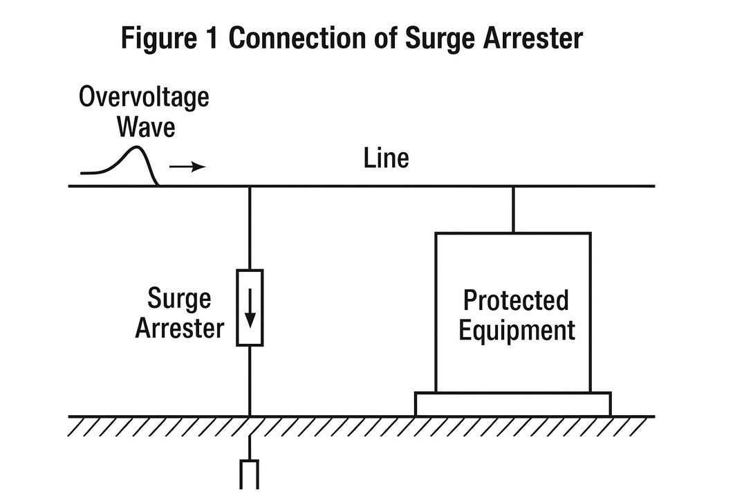
When lightning overvoltage intrudes into substations or other buildings along overhead lines, flashover may occur and even break down the insulation of electrical equipment. Therefore, if a protective device (surge arrester) is connected in parallel at the power supply inlet of electrical equipment, as shown in Figure 1, the arrester will immediately operate when the overvoltage reaches the specified operating voltage. It will conduct charge, limit the amplitude of the overvoltage, and protect the equipment insulation. Once the voltage returns to normal, the arrester will quickly restore itself to ensure normal system power supply.
The protective function of a surge arrester is based on three premises:
- Good coordination between its volt–second characteristic and that of the protected insulation.
- Ensuring that its residual voltage is lower than the impulse withstand strength of the protected insulation.
- The protected insulation must be within the protection distance of the surge arrester.
Requirements for Surge Arrester:
- No discharge under normal operation, but proper discharge when overvoltage occurs.
- Self-restoration capability after discharge.
Relevant Parameters of Surge Arrester:
- Continuous Operating Voltage: The maximum permissible long-term working voltage. It should be equal to or greater than the highest phase voltage of the system.
- Rated Voltage (kV): The maximum short-term power frequency voltage (arc-extinguishing voltage) permitted. The arrester can operate, discharge, and extinguish the arc under this voltage, but cannot operate under it continuously. This is the basic parameter of the arrester's characteristics and structure, and serves as the design basis.
- Power Frequency Withstand Volt–Second Characteristic: Indicates the ability of the zinc oxide arrester to withstand overvoltage under specified conditions.
- Nominal Discharge Current (kA): The peak discharge current used to classify the arrester grade.
Classification and structure of lightning arresters
Common types of lightning arresters include valve type, tube type, protective gap and metal oxide type, etc.
(1) Valve type lightning arrester
Valve type lightning arrester is mainly divided into two categories: ordinary valve type lightning arrester and magnetic blow valve type lightning arrester. Ordinary valve type lightning arrester has two series: FS and FZ; magnetic blow valve type lightning arrester has two series: FCD and FCZ.
The meanings of the symbols in the valve type arrester model are as follows:
- F - Valve-type lightning arrester;
- S - Distribution (transformation) function;
- Z - Power station use;
- Y - Line use;
- D - Rotating motor use;
- C - Has a magnetic blowout discharge gap.
A valve-type lightning arrester primarily consists of a flat spark gap connected in series with a silicon carbide resistor (valve disc). It is housed in a sealed porcelain tube, and the outer casing has terminal bolts for mounting. The silicon carbide resistor in the arrester has nonlinear characteristics: its resistance is high at normal voltage and decreases during overvoltage.
The spark gap of the valve type lightning arrester is not broken down under the normal power frequency voltage, but under the overvoltage of the lightning wave, the spark gap of the lightning arrester is broken down; the resistance value of the silicon carbide resistor becomes very small, and the huge lightning current of the lightning wave flows smoothly into the earth through the resistor. The resistor valve plate presents a large resistance to the power frequency voltage following the lightning current, so that the power frequency current is blocked by the spark gap and the line resumes normal operation. It can be seen that the close cooperation between the resistor valve plate and the spark gap makes the lightning arrester very similar to a valve. The 'valve' is open for the lightning current and closed for the power frequency current, so it is called a valve type lightning arrester.
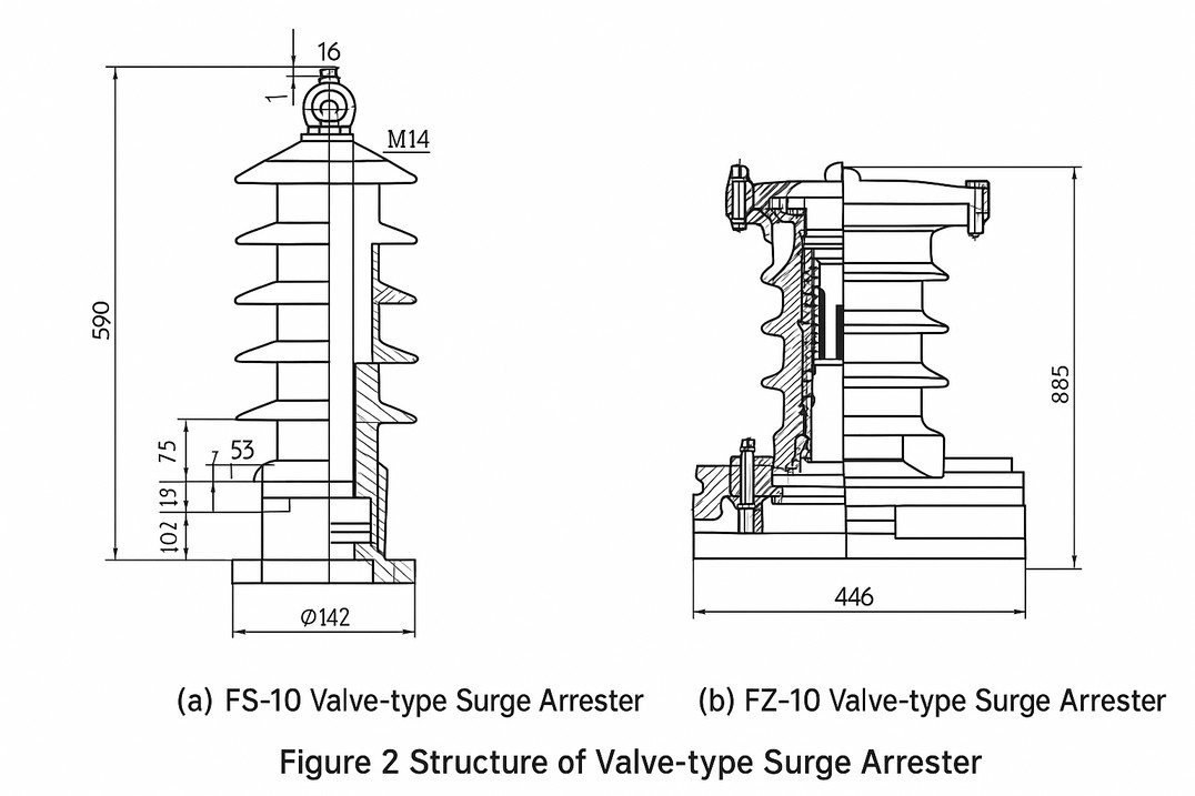
The structure of the FS series valve-type arrester is shown in Figure 2. This series of arresters has a smaller valve disc diameter and lower current capacity, and is generally used to protect power distribution equipment and lines. The structure of the FZ series valve-type arrester is shown in Figure 2 (b). This series of arresters has a larger valve disc diameter and a nonlinear silicon carbide resistor connected in parallel with the spark gap, resulting in a higher current capacity. It is generally used to protect electrical equipment in step-down substations in large and medium-sized factories with voltages of 35kV and above.
The magnetic blow-out valve arrester (FCD type) has a magnetic device inside to accelerate the extinction of the arc in the spark gap. It is specially used to protect important equipment or equipment with relatively weak insulation, such as high-voltage motors.
(2) Protective gap and tube-ball lightning arrester
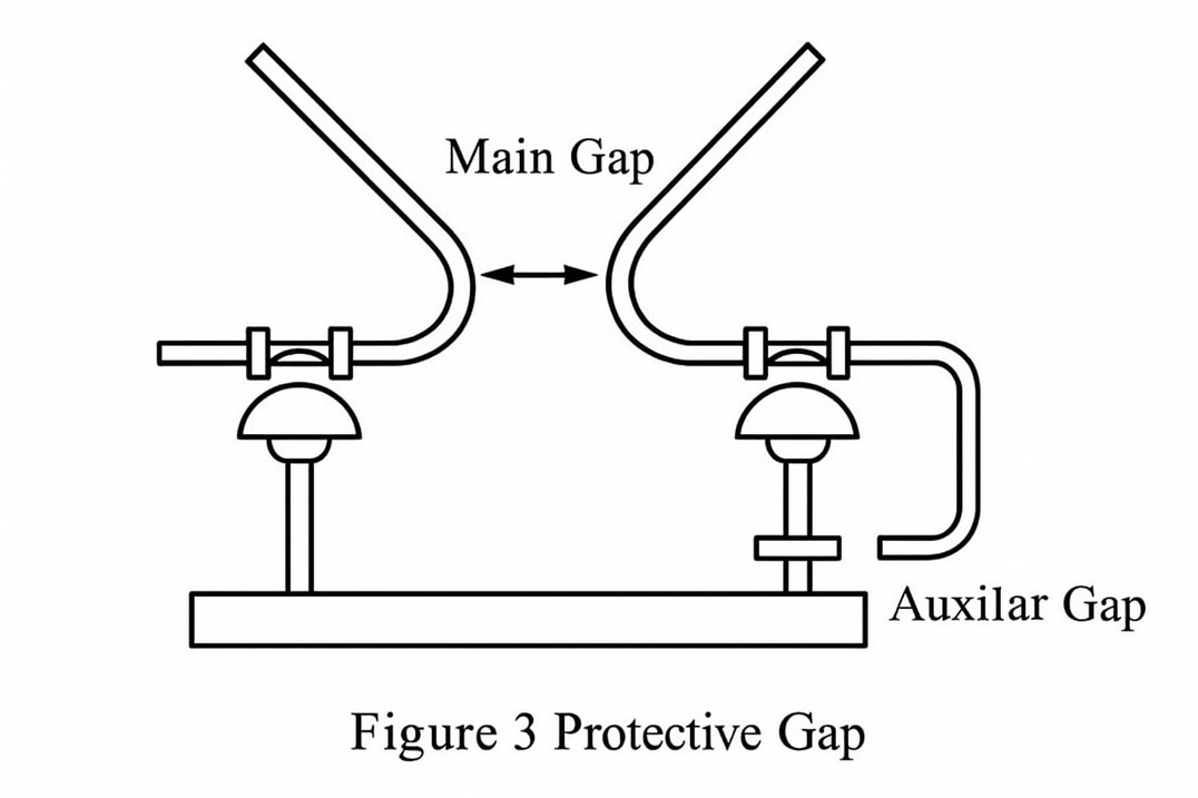
The protective gap is the simplest lightning protection device, and its principle structure is shown in Figure 3. The protective gap is generally made of galvanized round steel and consists of two parts: the main gap and the auxiliary gap. The main gap is made into an angle and installed horizontally to facilitate arc extinguishing. To prevent the main gap from being short-circuited by foreign objects and causing malfunction, an auxiliary gap is connected in series below the main gap. Because the protective gap has weak arc extinguishing ability, it is generally required to be used in conjunction with an automatic reclosing device to improve power supply reliability.
The basic component of a tubular arrester is a spark gap installed in a gas-producing tube. The gap is composed of rod-type and ring-type electrodes, as shown in Figure 4. The tubular arrester consists of an inner gap and an outer gap of the arc-extinguishing tube. The arc-extinguishing tube is generally made of materials such as fiber bakelite that can generate gas at high temperatures. When the lightning wave overvoltage arrives, the inner and outer gaps of the tubular arrester are broken down, and the lightning current is discharged into the earth through the grounding wire. The ensuing power frequency current generates a strong arc, which burns the tube wall and produces a large amount of gas ejected from the tube mouth, quickly blowing out the arc. At the same time, the outer gap restores insulation, isolating the arc-extinguishing tube or lightning arrester from the system, and the system resumes normal operation.
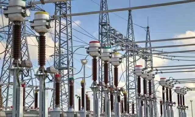
Metal Oxide Surge Arresters (MOA)
Metal oxide surge arresters (MOA) offer excellent protection, high current capacity, low residual voltage, compact size, and easy installation. Currently, MOA are widely used to protect both high- and low-voltage electrical equipment.
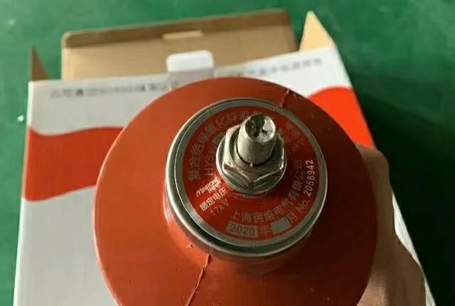
The model letters on the nameplate of a zinc oxide surge arrester, for example, HY5WS-17/50L, mean:
- H indicates a composite insulation jacket;
- Y indicates a metal zinc oxide surge arrester;
- 5 indicates a surge discharge current of 5kA;
- W indicates a gapless structure;
- S indicates a distribution type;
- 17 indicates a rated voltage of 17kV;
- 50 indicates a residual voltage of 50kV;
- L indicates a MOA with a disconnect device.
(2) The metal oxide (zinc oxide) arrester with a series gap is composed of a resistor plate in a composite jacket metal oxide arrester and a gap piece in series; the gap piece is two disc-shaped electrodes installed in a porcelain ring. It is suitable for neutral point non-effective grounding systems. When a single-phase grounding fault or arc grounding occurs in the system, a relatively serious transient overvoltage may be generated, and the duration is long. The zinc oxide arrester without a gap is difficult to withstand such an overvoltage. The zinc oxide arrester with a series gap overcomes the above disadvantages. Under single-phase grounding and arc grounding overvoltages of lower amplitude, the series gap does not operate, isolating the arrester from the system; under overvoltages higher than the above, the gap discharges, and the excellent volt-ampere characteristics of the zinc oxide valve plate limit the residual voltage at both ends of the arrester. The follow-on current value through the arrester is very small and can be easily cut off, providing reliable protection for the insulation of the transformer.
Test items and standards for lightning arresters
- Measure insulation resistance. Use a 2500V or higher megohmmeter. For 35kV and above, the resistance should not be less than 2500mΩ; for 35kV and below, the resistance should not be less than 1000mΩ.
- Measure the DC voltage of 1mA and the leakage current at 75% of the voltage. Apply DC voltage to the lightning arrester. As the voltage increases, the leakage current gradually increases. When the current reaches 1mA, record the voltage value. Then reduce the voltage to 75% of the voltage value and record the leakage current. The value should not be greater than 50μA.
- When the resistive current increases to 150% of the initial value, the monitoring period should be appropriately shortened.
The above tests can detect defects such as dampness and aging of the lightning arrester valve plate, cracks on the lightning arrester surface and insulation aging.
Author:
Guangzhou Aputon Electrical Co.,Ltd.


CONTACT
Office-ADD: Second floor, Jiutan Village, Xiuquan Street, Huadu District, Guangzhou, Guangdong, China
Factory-ADD: Fenjiangbei Road No.91, Chancheng, Foshan, Guangdong, China
(formerly State-owned Foshan Transformer Factory)
![]() Phone: +86-15876591363
Phone: +86-15876591363
00 1 (323) 841-2808
![]() E-mail: Tony@aputon-transformer.com
E-mail: Tony@aputon-transformer.com
Lily@aputon-transformer.com


 WhatsApp
 E-mail