![]() Tel: +86-15876591363
Tel: +86-15876591363 ![]() Email: Tony@aputon-transformer.com
Email: Tony@aputon-transformer.com

- English
- 简体中文
- عربي
- БеларускаяName
- Русский язык
- Français
- ខ្មែរKCharselect unicode block name
- ກະຣຸນາ
- Ruwanda
- Malay
- বাংলা
- ဗာရမ်
- Zulu, eNingizimu Afrika
- Português
- 日本語
- ภาษาไทย
- Español
- IndonesiaName
- Tiếng Việt
- 繁体中文
Basic knowledge of distribution transformers that you need to know
2025-09-26 09:21:30
Click:
1. Overview
A power transformer, or 'distribution transformer' for short, is used in power distribution systems to convert medium-voltage power into low-voltage power to power various low-voltage electrical equipment. Distribution transformers have a small capacity, generally 2500 kVA or less, and a relatively low primary voltage, typically 20 kV or less.
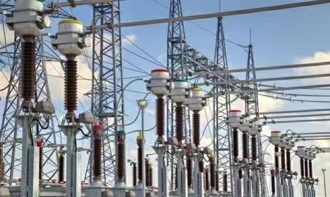
▲Figure Transformer
The transformer is made according to the electromagnetic induction principle of 'moving electricity generates magnetism, and moving magnetism generates electricity'.
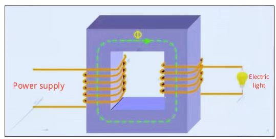
▲Figure Transformer working principle
The location and place where a distribution transformer is installed is the substation. Distribution transformers are preferably mounted on poles or on the ground in the open air. This article details their installation methods, installation precautions, power supply and distribution methods, capacity selection, and operation and maintenance.
2. Classification
Distribution transformers are divided into oil-immersed transformers and dry-type transformers according to the different insulation media; according to the different voltage regulation methods, they are divided into off-excitation voltage-regulating transformers and on-load voltage-regulating transformers.
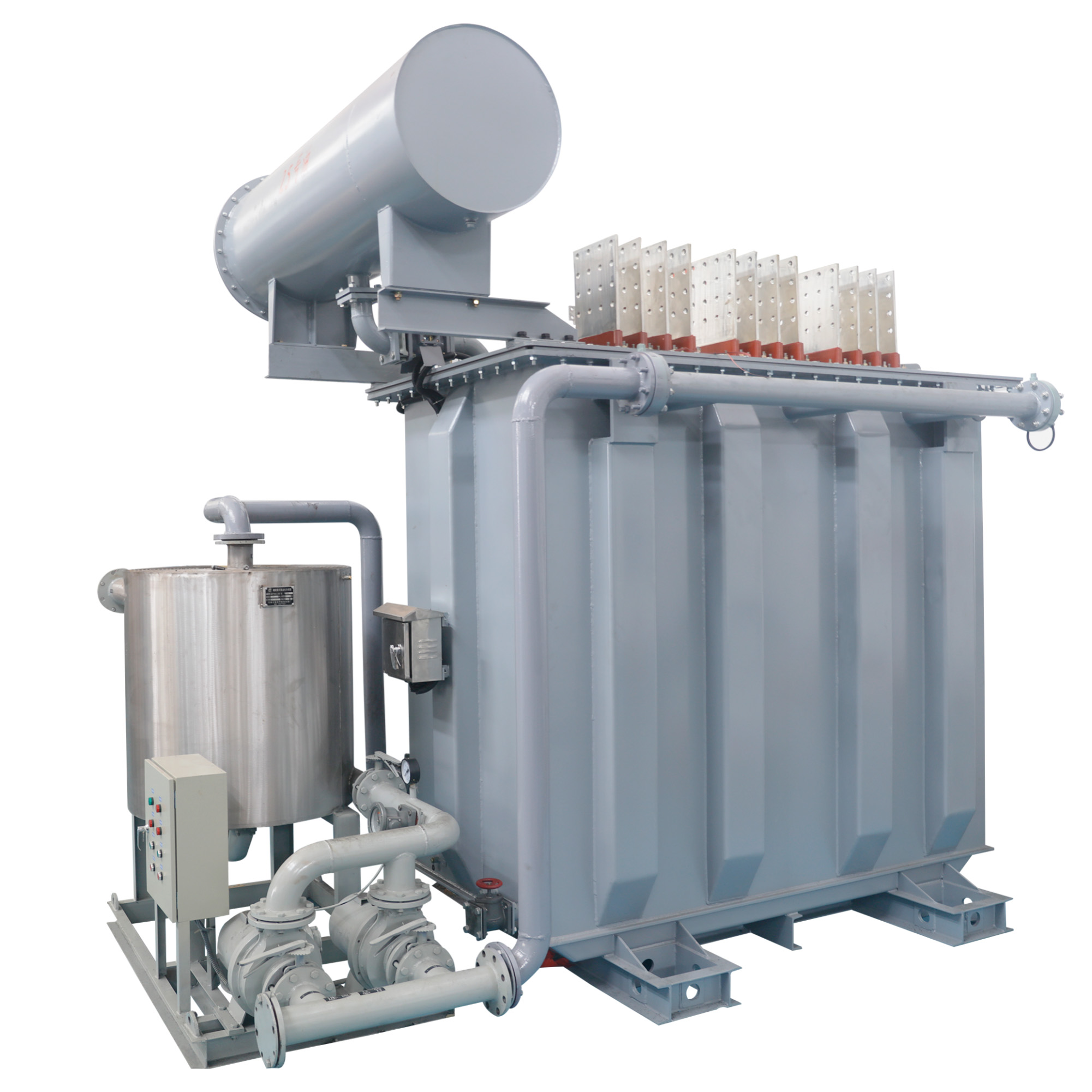
(1) Oil-immersed transformer
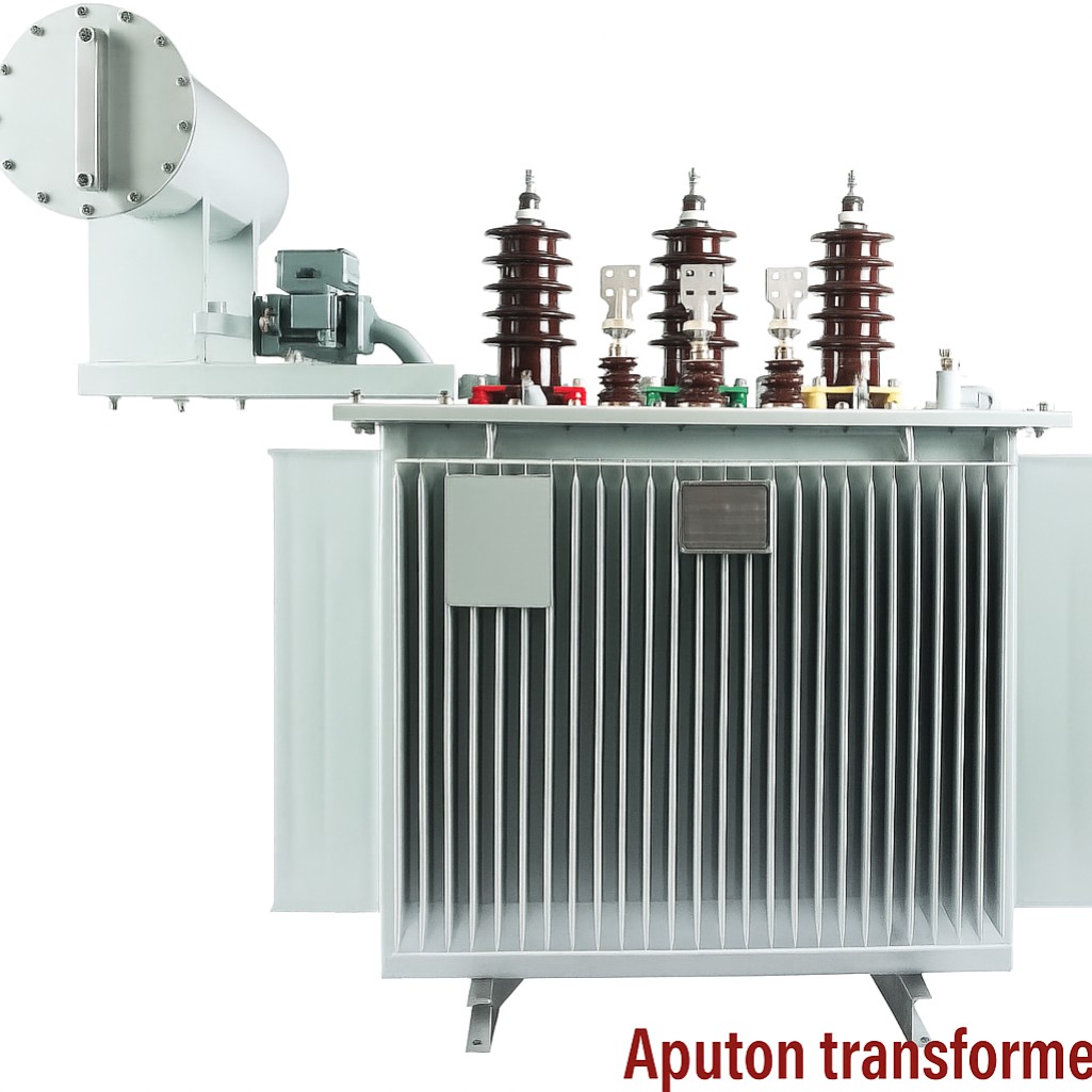
▲Picture Oil-immersed transformer
- Non-enclosed oil-immersed transformers: These primarily include the S8, S9, and S10 series, which are widely used in industrial and mining enterprises, agriculture, and civil construction.
- Enclosed oil-immersed transformers: These primarily include the S9, S9-M, and S10-M series, which are often used in oil- and chemical-intensive environments within the petroleum and chemical industries.
- Sealed oil-immersed transformers: These primarily include the BS9, S9-, S10-, S11-MR, SH, and SH12-M series, which are used for power配电 in various locations, including industrial and mining enterprises, agriculture, and civil construction.
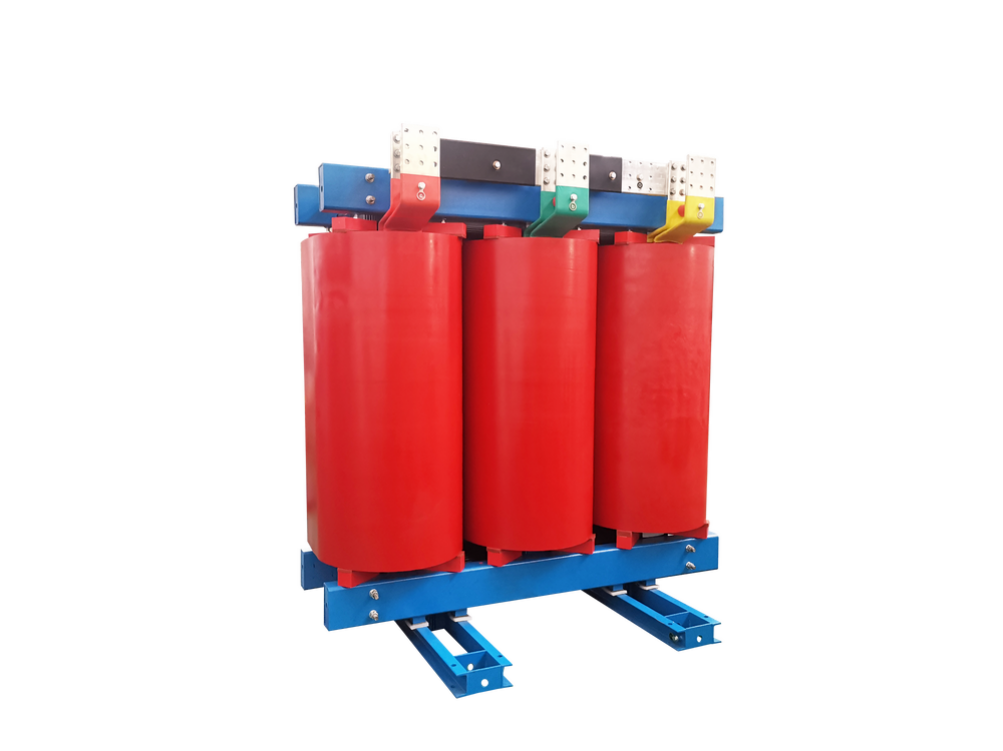
(2) Dry-type transformer
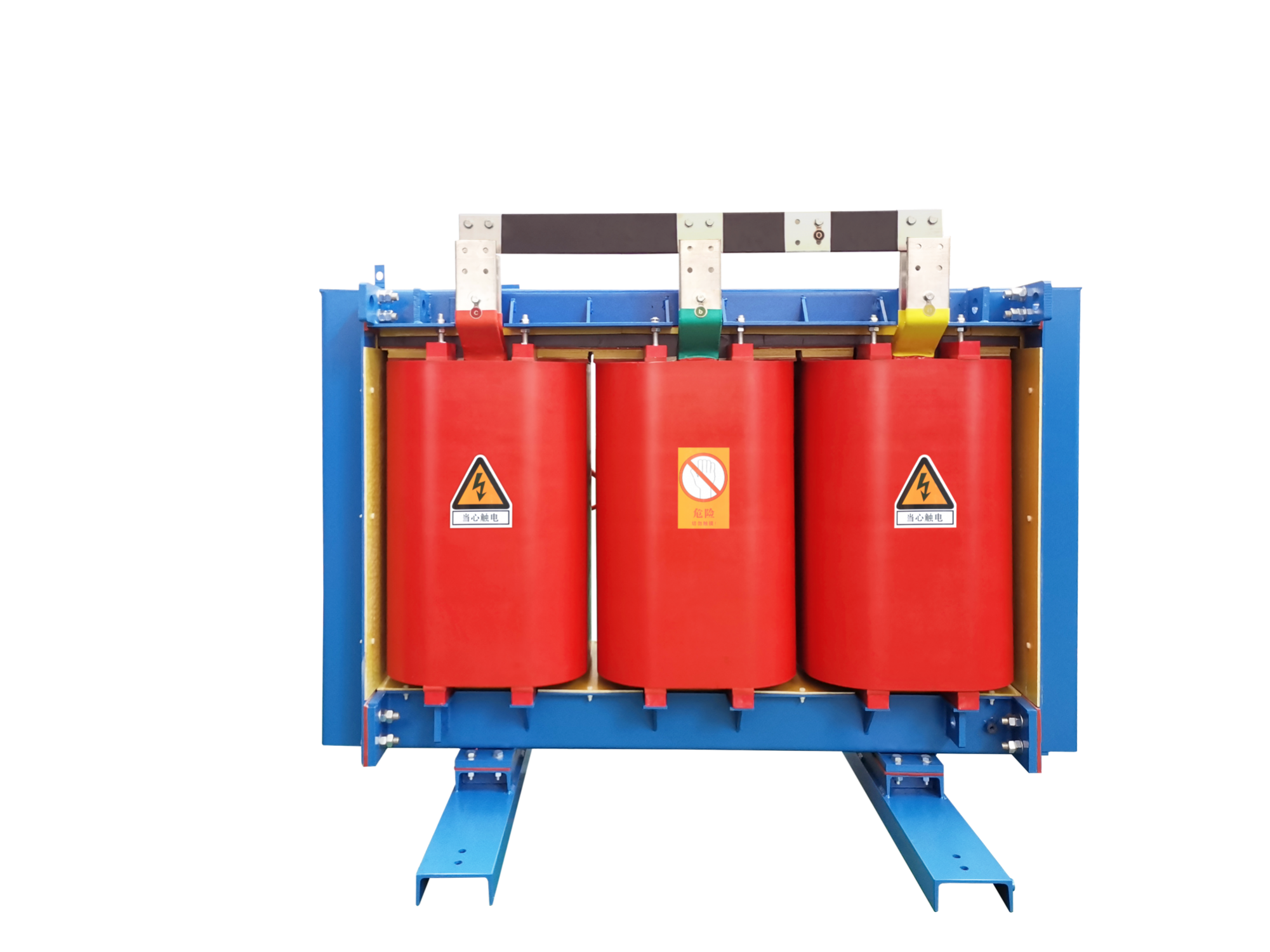
▲Figure Dry-type transformer
- Encapsulated Coil Dry-Type Transformers: These primarily include the SCB8, SC(B)9, SC(B)10, and SCR-10 series, suitable for use in high-rise buildings, commercial centers, airports, stations, subways, hospitals, and factories.
- Non-Encapsulated Coil Dry-Type Transformers: These primarily include the SG10 series, suitable for use in high-rise buildings, commercial centers, airports, stations, subways, and petrochemical facilities.
3. Basic Structure
The structure of a distribution transformer consists of three parts: the core, windings, and insulating oil. The windings are the transformer's electrical circuit, and the core is the transformer's magnetic circuit. The two constitute the core of the transformer, namely the electromagnetic part.
3.1 Iron Core
The iron core is one of the basic components of the transformer and is the main magnetic circuit part of the transformer. It is both the main magnetic flux of the transformer and the mechanical skeleton of the transformer body.
It is usually made of hot-rolled or cold-rolled silicon steel sheets with a high silicon content, a thickness of 0.35 or 0.5 mm, and an insulating paint coated on the surface. The iron core is divided into two parts: the iron core column and the iron yoke. The iron core column is covered with windings, and the iron yoke is used to close the magnetic circuit.
According to the structure, it can be divided into: core type and shell type
Heart type - simple structure, simple process and wide application.
Shell type - complex structure, used in small capacity transformers and electric furnace transformers.
According to the material, it can be divided into: silicon steel sheet, amorphous alloy
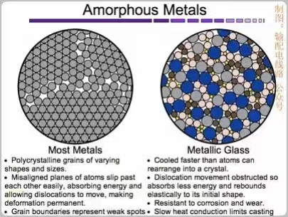
▲Figure Transformer materials
Amorphous alloys solidify by ultra-rapid cooling. During solidification, the atoms in the alloy do not have time to arrange themselves in an orderly manner and crystallize. The resulting solid alloy has a long-range disordered structure, lacking the grains and grain boundaries of crystalline alloys.
Amorphous alloy core transformers use a new magnetically conductive material—amorphous alloy—to create their cores. Compared to transformers with silicon steel cores, these transformers reduce their no-load losses (the power loss measured in the primary when the secondary is open) by approximately 75% and their no-load current (the current remaining in the primary when the secondary is open, known as the no-load current) by approximately 80%, making them one of the most energy-efficient distribution transformers currently available.
According to the assembly process, it can be divided into: stacking type, winding type
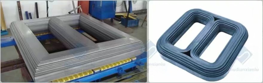
▲Figure Assembly process
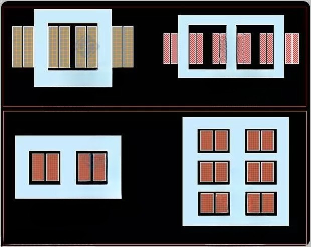
3.2 Winding
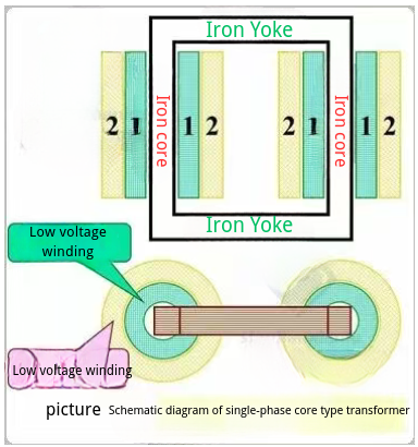
The windings form the circuitry of a transformer, typically wound around a winding mold using insulated flat or round copper wire. The windings are mounted on the transformer core, with the low-voltage winding on the inner layer and the high-voltage winding on the outer layer. Insulating sleeves separate the low-voltage winding from the core, and the high-voltage winding from the low-voltage winding for insulation. There are two basic types of windings, depending on the relative placement of the high-voltage and low-voltage windings on the core: concentric and overlapping.
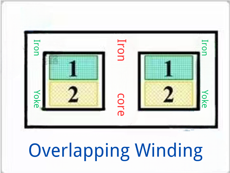
(1) Overlapping
The overlapping type is also called pancake winding. The high-voltage winding and low-voltage winding are each divided into several pancakes, which are arranged in a staggered manner along the height of the core. The overlapping winding is mostly used in shell-type transformers.
Both the high-voltage winding and the low-voltage winding are made into cylindrical shapes, but the diameters of the cylinders are different, and then they are coaxially sleeved on the iron core column.
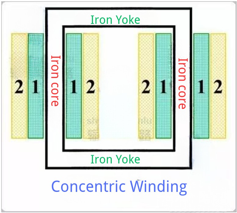
(2) Concentric type
Concentric winding can be divided into several forms according to its winding characteristics, such as cylindrical, spiral, connected and tangled types.
Cylindrical winding is the simplest type of winding. It uses insulated wire to continuously wind along the height of the core. After the first layer of winding is completed, interlayer insulation paper is placed before the second layer of winding is completed. This type of winding is generally used for low-voltage windings in small-capacity transformers.
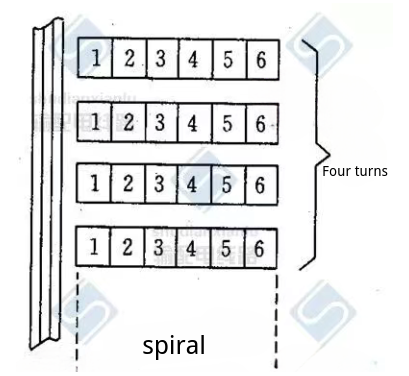
The spiral winding has a large number of parallel wires in each turn. It is made by arranging multiple insulated flat wires in parallel along the radial direction (one on top of another), and then winding them one turn after another along the axial height of the iron core column like a thread. One turn is like a coil.
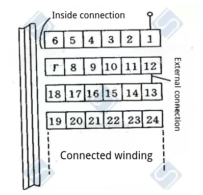
The connected winding is composed of several coils wound continuously with flat wire. The connections between adjacent coils are alternately on the inside and outside of the winding, and are naturally connected by the wire wound around the winding without joints.
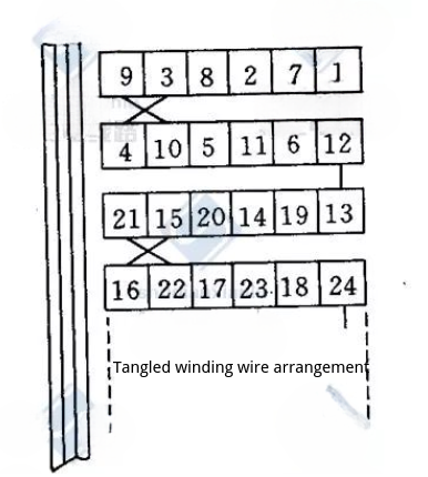
The appearance of the tangled winding is similar to that of the continuous winding. The main difference is that another turn of the winding is inserted between the electrically adjacent turns of the tangled winding.
3.3 Casing
The bushing is the insulating support for the transformer lead wire. It not only insulates the lead wire from the ground, but also holds the lead wire in place. Therefore, the transformer bushing must have high electrical and mechanical strength as well as good thermal stability.
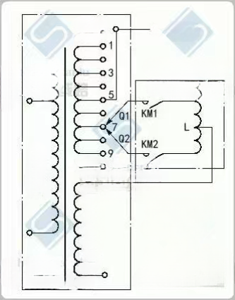
3.4 Pressure regulating device
A distribution transformer's voltage regulator, also known as a tap changer, is a regulating component that controls the transformer's output voltage within a specified range. It operates by varying the turns ratio of the primary and secondary windings to adjust the transformer's voltage, thereby achieving voltage regulation.
The voltage regulating devices of distribution transformers are divided into two types: no-load voltage regulating devices and on-load voltage regulating devices. The no-load voltage regulating device, commonly known as the no-load tap-changer, switches the coil taps in the winding to achieve voltage regulation when the transformer is not energized, and is usually operated manually. The on-load voltage regulating device, also known as the on-load tap-changer, regulates the voltage while the transformer is energized and operating.
4. Technical Parameters
The main technical parameters of distribution transformers include: number of phases, rated frequency, rated capacity, rated voltage, rated current, impedance voltage, load loss, no-load current, no-load loss and connection group.
5. Connection Group
There are two main ways to connect the windings of a three-phase distribution transformer: star connection and triangle connection.
(1) Star connection
Star connection, represented by Y, is to connect the ends (or the beginning) of the three-phase windings together to form a neutral point. The other three wire ends are lead-out wires. When there is a neutral wire lead-out on the low-voltage side, it is represented by n. The Yyn0 connection group is shown in the figure below.
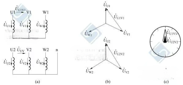
▲ Figure Yyn0 Contact Group
(a) Winding connection diagram; (b) Voltage phasor diagram; (c) Clock representation
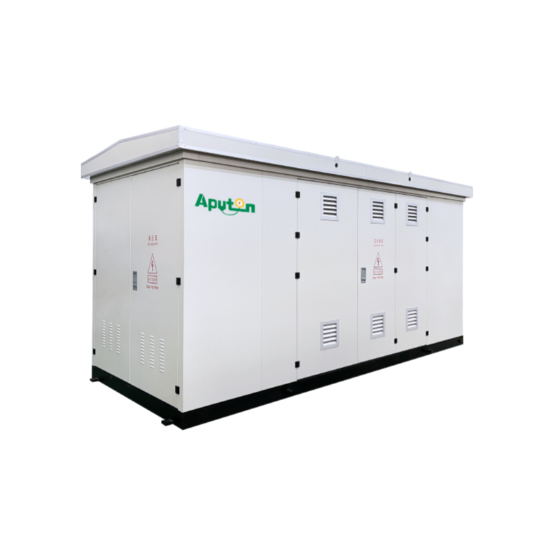
6. box-type substation
A box-type substation, also known as a box-type transformer station, prefabricated substation, or prefabricated substation, or simply 'box-type transformer,' is a complete set of power distribution equipment consisting of a transformer, high-voltage voltage control equipment, and low-voltage voltage control equipment. Its basic principle is to assemble the pressure-activated system, armored cables, substation automation system, DC points, and corresponding technical equipment in a prescribed sequence. All components are then installed in a specially sealed, waterproof, dustproof, and rodent-proof tempered enclosure to create a specific transformer.
7. Amorphous alloy transformer
The amorphous alloy distribution transformer adopts the Dyn11 connection group. Its most outstanding feature is that its no-load loss and no-load current are much lower than those of silicon steel sheet core transformers. Its no-load loss is 60% to 80% lower than that of traditional silicon钢 core transformers. CO2 and SO2 emissions are greatly reduced, with obvious energy-saving and environmental protection effects.
8. Dry-type transformer
Dry-type distribution transformers offer a wide range of adaptability, including strong thermal shock resistance, high overload capacity, flame retardancy, high fire resistance, and insensitivity to humidity and dust. They are ideal for use in harsh environments with high fire protection requirements, large load fluctuations, and dirt and humidity.
9. Installation method
Under normal circumstances, distribution transformers should be installed on poles or on the ground in the open air. Distribution transformers in factories, workshops, and suburban living areas can be installed indoors depending on the specific situation. The components and features of a distribution transformer installed on a pole or on the ground in the open air: Pole installation:
(1) Single column
The transformer, high-voltage drop-out fuse, and high-voltage lightning arrester are installed on the same pole. It has a simple structure, is easy to install, requires less material, and takes up less space. It is suitable for installing distribution transformers below 50KVA.
(2) Double columns
The double pole consists of a high-voltage line terminal pole and another auxiliary pole (about 7.5 meters long). It is stronger than the single pole and can install 63-315KVA distribution transformers. The transformer is directly placed on a platform (pier) with a height of not less than 2.5 meters. It is easy to disassemble and assemble the transformer, and the transformer capacity is not limited.
Author:
Guangzhou Aputon Electrical Co.,Ltd.


CONTACT
Office-ADD: Second floor, Jiutan Village, Xiuquan Street, Huadu District, Guangzhou, Guangdong, China
Factory-ADD: Fenjiangbei Road No.91, Chancheng, Foshan, Guangdong, China
(formerly State-owned Foshan Transformer Factory)
![]() Phone: +86-15876591363
Phone: +86-15876591363
00 1 (323) 841-2808
![]() E-mail: Tony@aputon-transformer.com
E-mail: Tony@aputon-transformer.com
Lily@aputon-transformer.com


 WhatsApp
 E-mail